
Calculations, Procedure, and Results
Summary:
The analyses done throughout the project were to guide the design and find the numerical values of each requirement of the deployment system. To properly analyze the design there were free body diagrams of the payload, counterweight, and deployment system itself.
Requirements include:
-
Deployment system must withstand the forces from each launch.
-
Deployment system must have a counterweight.
-
The spring within the deployment system must have enough force to push the nose cone out.
-
Enclosure supports must leave enough room for payload and deployment.
-
Deployment system must not damage the electrical equipment aboard the payload and the outer shell of the rocket.
-
Deploy after the rocket lands.
-
Be fully retained until the intended point of deployment.
-
Payload deployment system must fit completely inside the rocket.
-
Be able to handle the force of the launch.
-
Materials must be strong enough to withstand the force of the deployment.
Analyses
Analysis 1:
The rocket deployment system must be able to withstand falling from a force equal to that it undergoes while it is in the body of the rocket is launching. The calculated force using Newton’s Second Law (F = ma) was roughly 1,500 lb*ft/s. See Appendix A1.

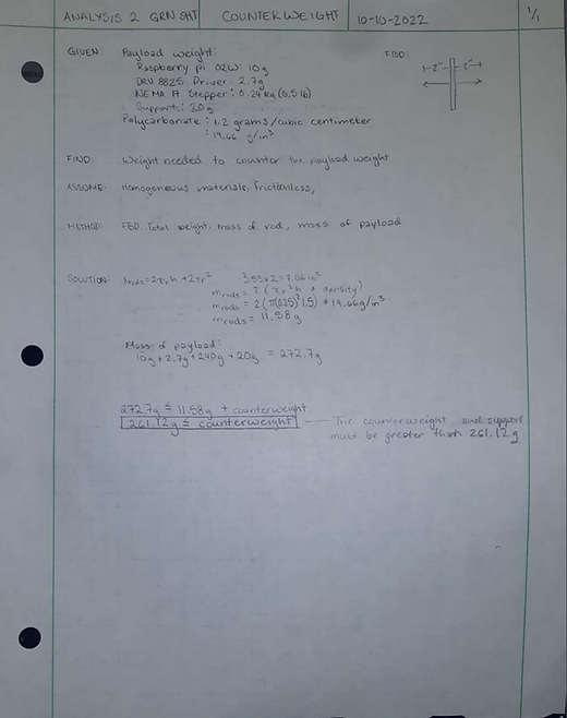
Analysis 2:
The rocket deployment system must have a counterweight to ensure the protective wall faces the ground. The counterweight and counterweight support must have a mass greater than 261.12 grams. The counterweight value was calculated by summing the masses and creating a balance equation.
Analysis 3:
The rocket deployment system must have enough force to push the nose cone from the body of the rocket. The force was calculated to be 0.33 kg*m/s2. The force was calculated by calculating the total weight of each part in movement then using Newton’s Second Law of Motion to calculate the total force.

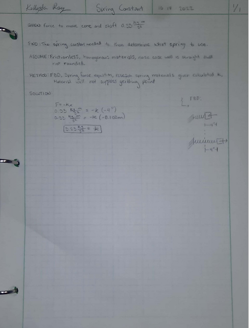
Analysis 4:
The payload deployment system needs a spring to deploy the nose cone. To decide on the spring to be used the spring constant had to be calculated. The spring constant was calculated to be 3.23 kg/s2. The spring constant was calculated by taking the weight and force calculated in Analysis 3(See Appendix A3) and using Hooke’s Law to find the spring constant.
Analysis 5
The Shear Force Inner Shaft requirement was to be able to withstand the shear forces applied to the Inner Shaft. The green sheet analysis calculated the cross-sectional area and the past calculated force to complete the shear stress analysis. The design of Inner Shaft will be able to withstand the shear stress of 0.094 psi. The information was documented in Appendix A5.

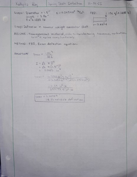
Analysis 6
The Spring Shaft Deflection requirement was to be able to handle the deflection from the weight of the nosecone without causing failure or permanent deflection. The green sheet analysis calculated the moment of inertia and using the previously calculated variables to complete the deflection analysis at the end of the shaft. The design of the shaft was able to withstand the deflection due to the deflection being equivalent to zero. The information on the analysis was documented in Appendix A6.
Analysis 7
The Axial Loading Spring Shaft requirement was to be able to handle the axial loading. The green sheet analysis calculated the cross-sectional area deflection using axial loading analysis with the previously calculated and given variables such as force, length, and modulus of elasticity. The design of the inner shaft was able to handle the change in area due to being equivalent to zero in relation to the original cross-sectional area of 0.785 inches squared. The information of the axial loading was documented in Appendix A7.
Note: Analysis 4 involving the Spring Shaft was obsolete due to changing the design to a linear actuator and changing out the Spring Shaft.


Analysis 8
The Base Shaft Deflection requirement was to be able to withstand the deflection cause by the payload counterweight and payload weight. The green sheet analysis included calculated the moment of inertia and by using the previously calculated values such as modulus of elasticity, length, and weight deflection analysis was completed. The design of the shaft was able to withstand the deflection of 0.37 inches due to the strength and length (6 inches) of the polycarbonate. The information on the analysis was documented in Appendix A8.

Analysis 9 The Wire Gauge Actuator requirement was to be able to send electrical current from the raspberry pi to the actuator. The green sheet analysis included the given Amps from the part and used American Wire Gauge system analysis from Table 2.1 of the Electronics Technology Fundamentals textbook. The design of the part will not change since the part was bought though the wire will be extended by using gauge 18 wiring. The information pertaining to the analysis was documented in Appendix A9 and Appendix B13.

Analysis 10
The Shear in Pin (Bolt) requirement was to be able to handle the shear force from the linear actuator force. The green sheet analysis calculated the double shear the bold would face to find the force the bolt must withstand and compared aluminum versus steel to find what material the bold must be. The design was influenced by this calculation due to aluminum being strong enough to withstand the forces of the linear actuator and being lighter than steel. The information pertaining to the analysis was documented in Appendix A10 and the part is documented in Appendix B13.

Analysis 11:
The Actuator Deflection requirement was to be able to withstand the forces acting on the end of the actuator by the nose cone. The green sheet analysis included the modulus of elasticity of aluminum, the length of the actuator and the weight of the nose cone. Using the given information, a deflection analysis was completed. The design of the part did not need to be changed after completing the analysis due to the deflection being miniscule (equivalent to zero). The information on the analysis was documented in Appendix A11. The actuator the analysis pertains to is documented in Analysis B13.

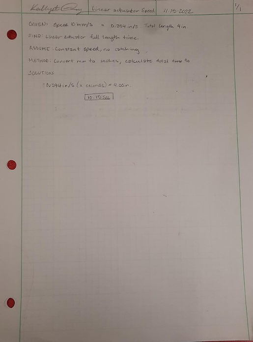
Analysis 12
The Linear Actuator Speed requirement was to be less than 20 seconds to fully deploy (4 inches) ensuring to payload can receive code and act accordingly. The green sheet analysis was completed by taking the actuator speed of 10 mm/s and calculating how many seconds it would take to extend the total 4 inches. The time calculated was 10.15 seconds, the design did not have to be changed due to the short amount of time the linear actuator takes to reach 4 inches. Analysis 12 was documented in Appendix A12; the linear actuator was documented in Analysis B13.
Analysis 13
The Axial Loading Extension requirement was to not deflect 0.0125 inches. The green sheet analysis was completed by calculating the cross-sectional area deflection using axial loading analysis with the previously calculated and given variables such as force, length, and modulus of elasticity. The design of the Extension shaft was able to handle the change in area due to the likelihood of the nose cone getting caught on something in an open field. The cross-sectional area was calculated to be 0.636 inches squared. The information of the axial loading was documented in Appendix A13.
